Technical data
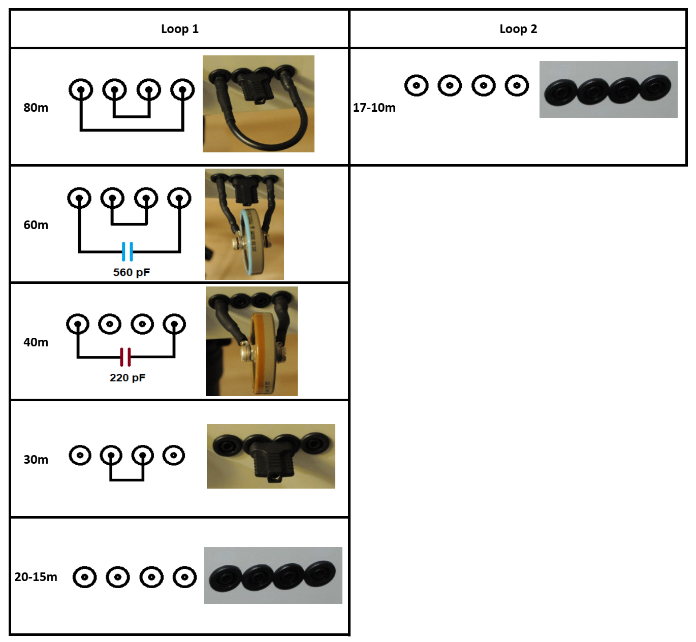
| Supported Bands | 80m, 60m, 40m, 30m, 20m |
| Max. Power [W] | 45 |
| Diameter of loop | 80cm (2.6 feet) |
| Number of turns | 2 |
| Power Supply | 230VAC / 12-26VDC* |
| *at least 22V needed for 80m band | |
Introduction
In my previous home I was limited with antennas only to the balcony and apartment space, it was not possible to place a wired antenna. My existing MLA was indoor only. I decided to build a new MLA for the balcony to get more signal. The requirements were that it should be weatherproof, have remote tuning and be stealthy.
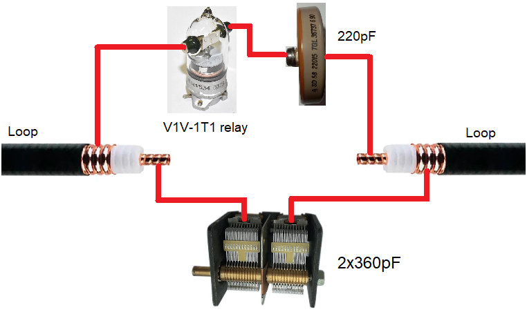
With previous good experience with Cellfex cable, I chose a smaller diameter 1/2″ (Cellflex SCF12-50) which is easier to work with than 7/8″. The choice fell on a double coil loop using both the center and outer conductor. I thought for a long time how to solve the band switching, until I came across a video where this was solved by connecting an additional capacitor via a vacuum relay. The disadvantage is that it needs a 24V supply.
-

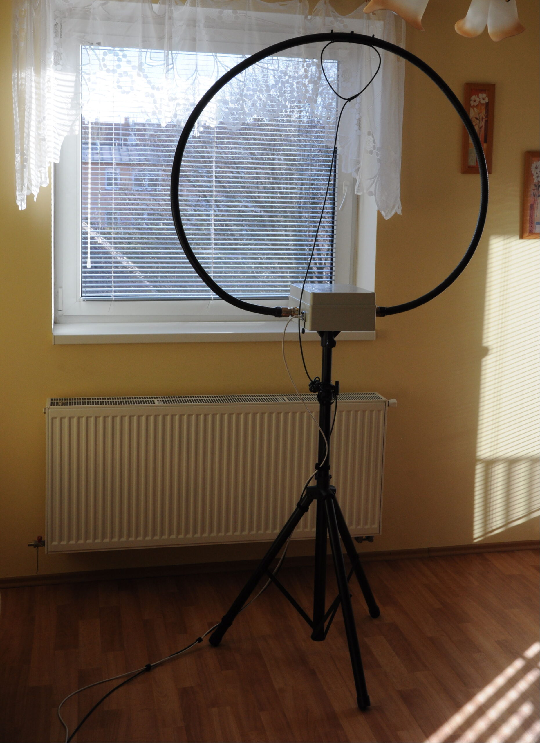
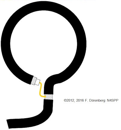
- MLA front view

-
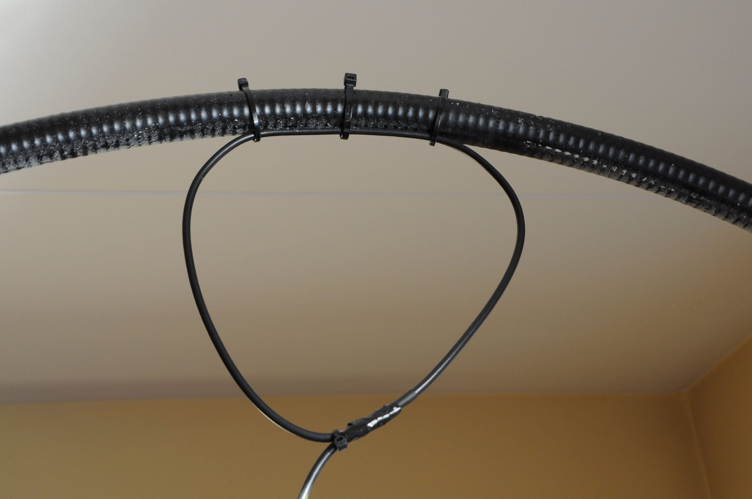
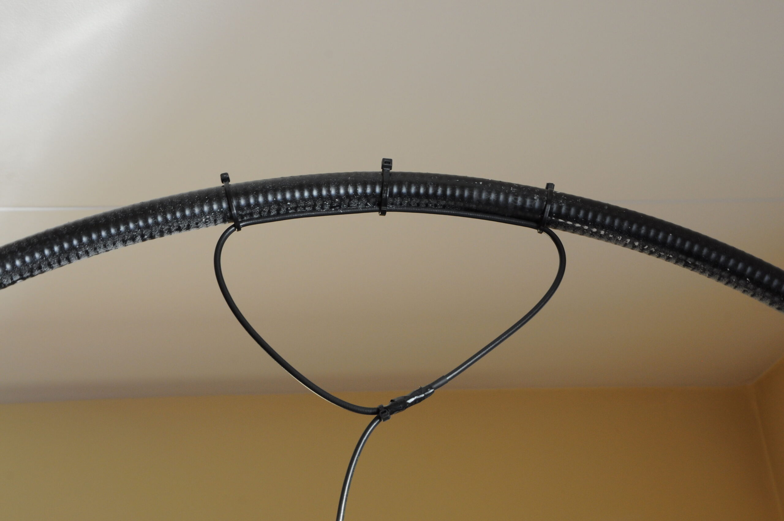
- Example of instalation

-
- MLA on speaker stand

-
- Inside MLA base

-
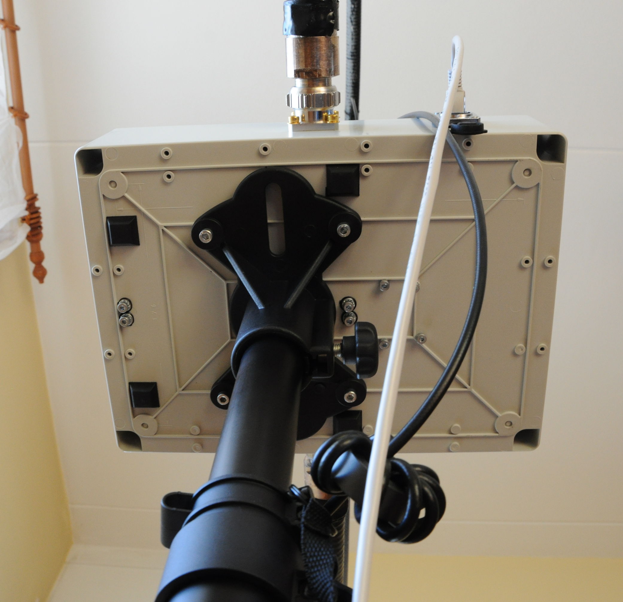
- Rear MLA base

-
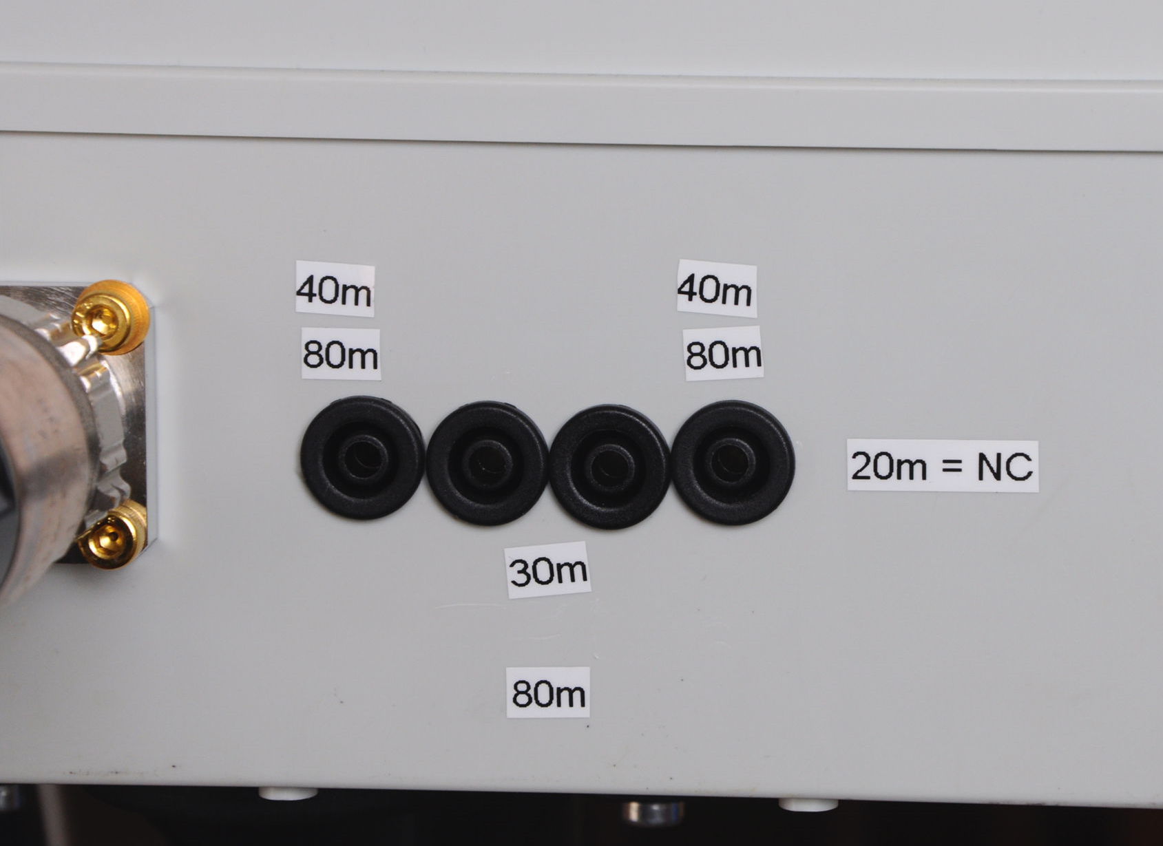
- Remote box – front panel

-
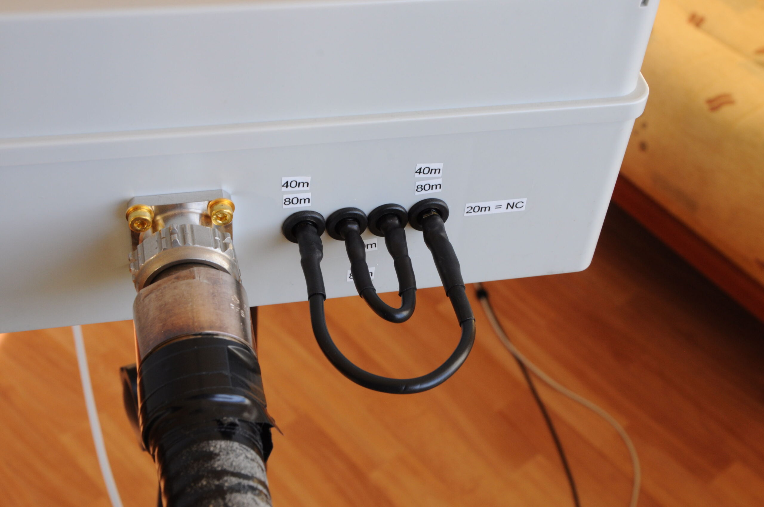
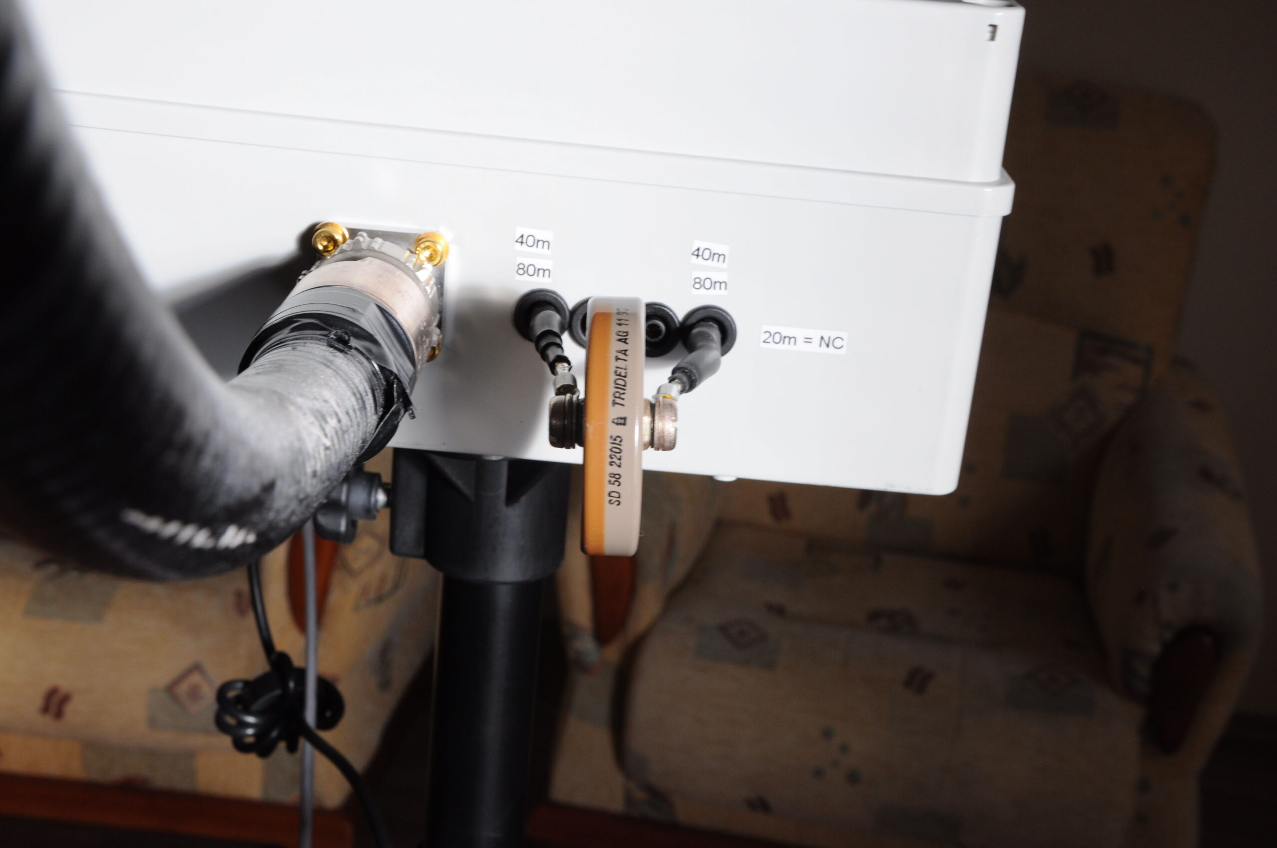
- Remote box – rear

-
- Inside the remote box

Construction
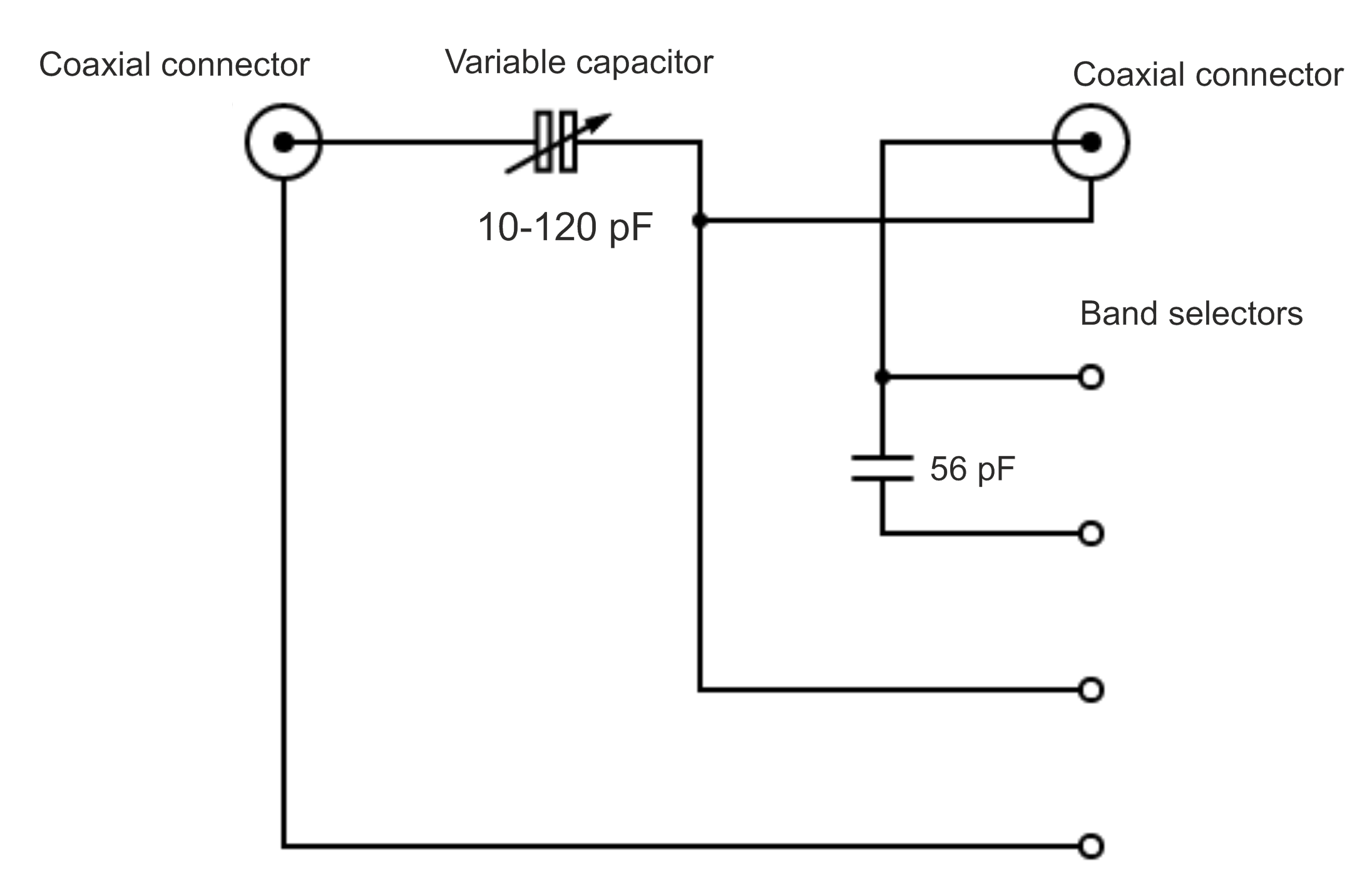
The two-loop MLA is made up of a total of 480 cm (15.7 feets) of Cellfex cable. The bottom thread is attached to the mounting box. Although the cable holds its shape, two plastic supports are added for better wind resistance. There are two mast mounts on the back of the box. Waterproof connectors for coaxial cable and RJ45 are used. To minimize losses, only two separate stators of the capacitor are connected.
For tuning I found the 28BYJ-48 stepper motor to be a good choice, its power is sufficient for most variable capacitors. It is produced in large quantities and is thus cheap. I use it in bipolar wiring (modification required), the DRV8825 is used as driver. Only one limit switch is used for calibration at the start position, the other end position is defined by software.
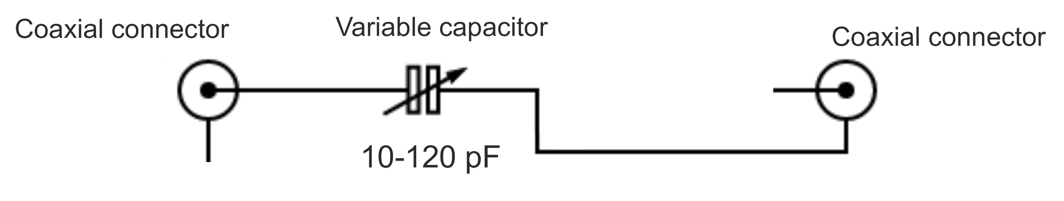
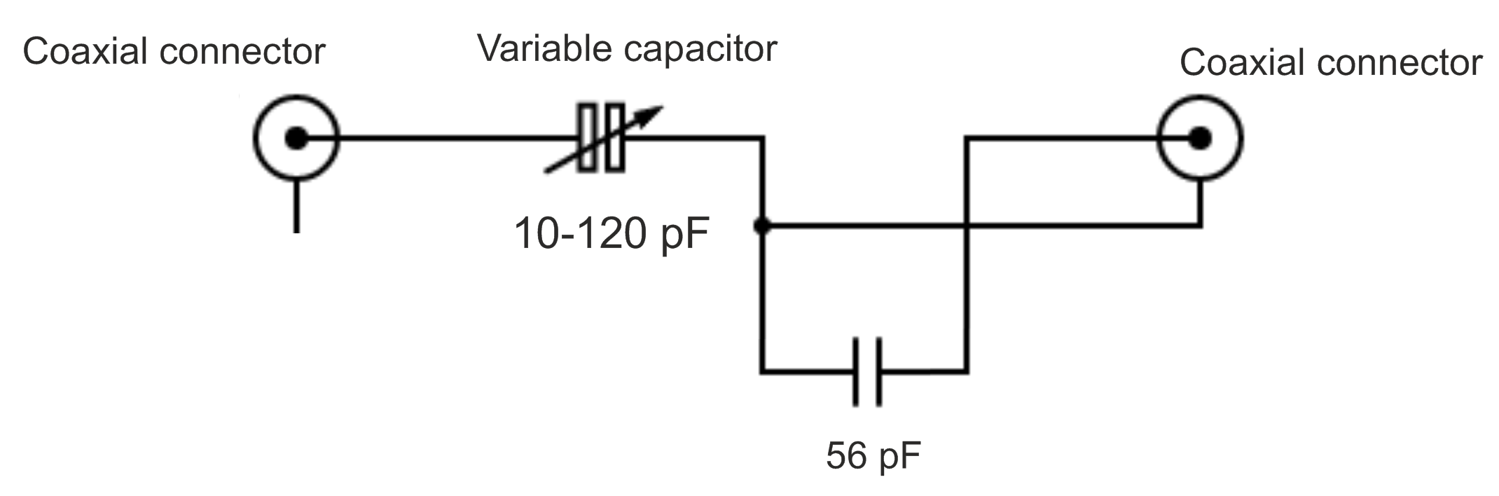
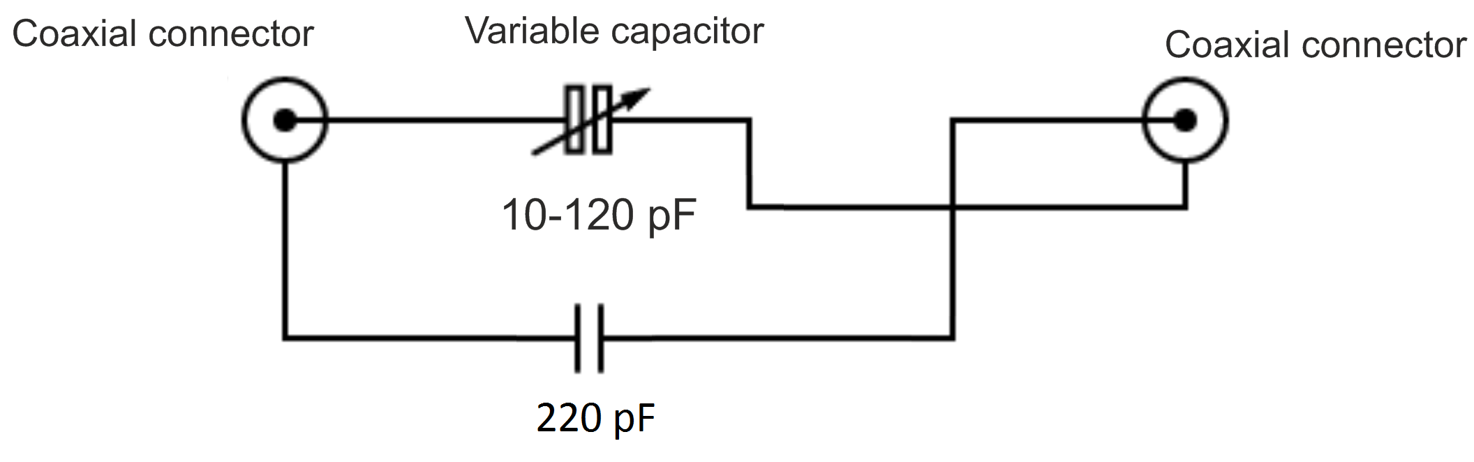
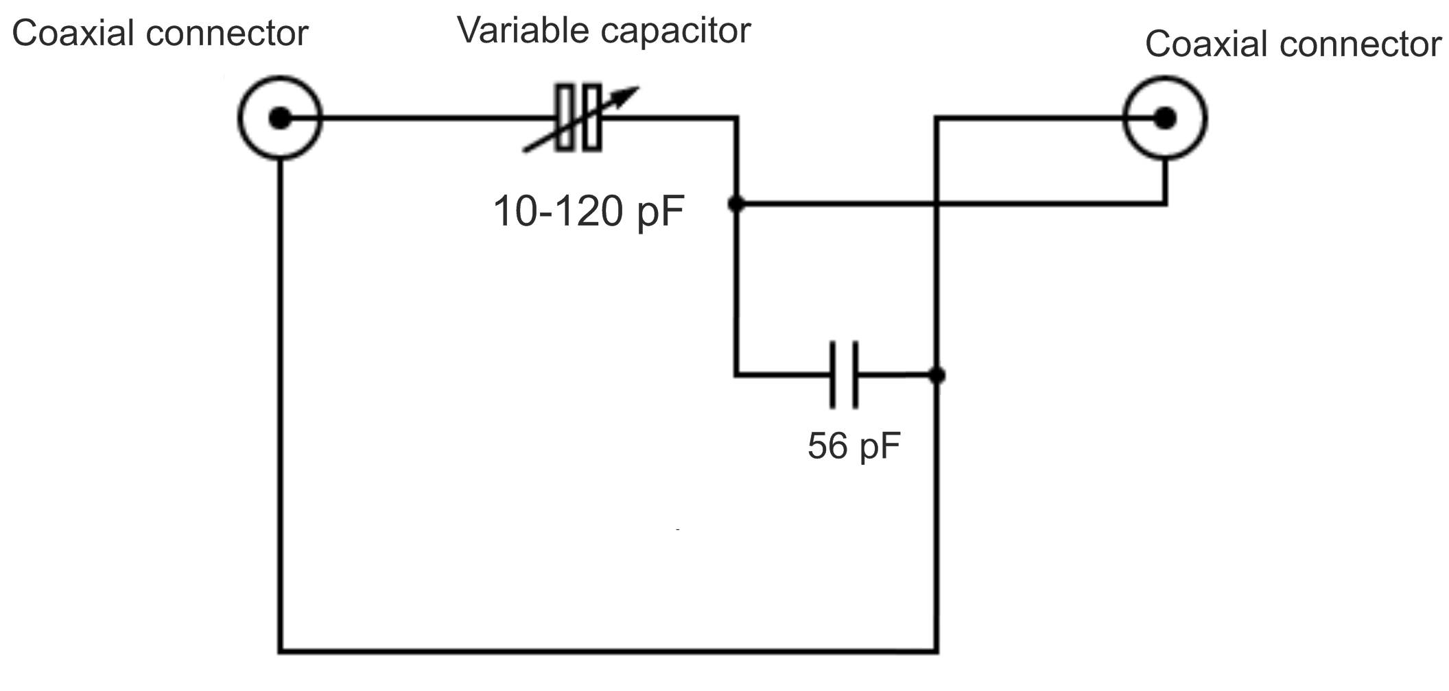
MLA circuit
Remote box
Since 24V is needed to control the relay, the power supply is solved via a mains transformer. It has connector for DC voltage also. The display shows the current position, band and approximate tuning frequency. For each band, a calibration curve (dependence of position on frequency) has been measured. The frequency is tuned with an optical encoder or push buttons. There is also a frequency calibration option.
The disadvantage of stepper motors with gearbox is the gearbox backlash, which must be solved in software. In SW I add extra steps when changing direction to compensate this backlash.
Conclusion
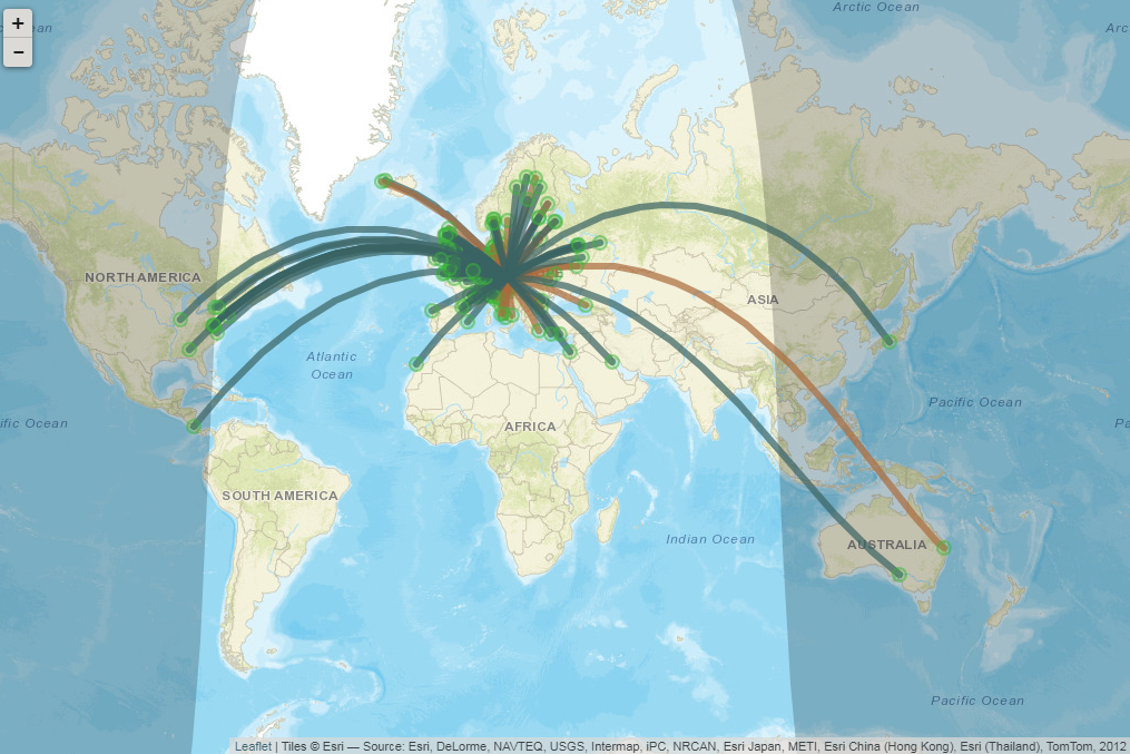
Compared to my previous MLA, I placed this one outside, which gave me a slightly better signal. It is suitable mainly for CW/FT8 mode operation, but SSB QSO is also possible. It should be noted that the MLA is a compromise antenna. I’ve operated with it mostly on local 80m contests, just for fun, and even then I’ve been able to make 30 contacts per hour. My furthest QSO was on 20m to K1.