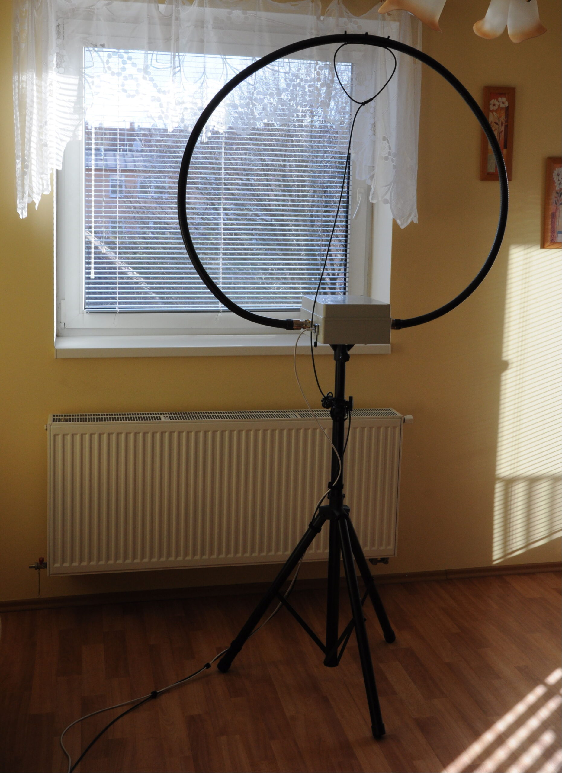
MLA balcony antenna

Technical data

Supported Bands80m, 60m, 40m, 30m, 20m
Max. Power [W]45
Diameter of loop80cm (2.6 feet)
Number of turns2
Power Supply230VAC / 12-26VDC*
*at least 22V needed for 80m band

Introduction

In my previous home I was limited with antennas only to the balcony and apartment space, it was not possible to place a wired antenna. My existing MLA was indoor only. I decided to build a new MLA for the balcony to get more signal. The requirements were that it should be weatherproof, have remote tuning and be stealthy.

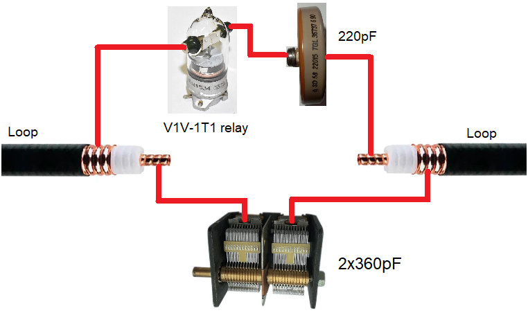
With previous good experience with Cellfex cable, I chose a smaller diameter 1/2″ (Cellflex SCF12-50) which is easier to work with than 7/8″. The choice fell on a double coil loop using both the center and outer conductor. I thought for a long time how to solve the band switching, until I came across a video where this was solved by connecting an additional capacitor via a vacuum relay. The disadvantage is that it needs a 24V supply.

Construction

The two-loop MLA is made up of a total of 480 cm (15.7 feets) of Cellfex cable. The bottom thread is attached to the mounting box. Although the cable holds its shape, two plastic supports are added for better wind resistance. There are two mast mounts on the back of the box. Waterproof connectors for coaxial cable and RJ45 are used. To minimize losses, only two separate stators of the capacitor are connected.

For tuning I found the 28BYJ-48 stepper motor to be a good choice, its power is sufficient for most variable capacitors. It is produced in large quantities and is thus cheap. I use it in bipolar wiring (modification required), the DRV8825 is used as driver. Only one limit switch is used for calibration at the start position, the other end position is defined by software.

MLA circuit

Remote box

Since 24V is needed to control the relay, the power supply is solved via a mains transformer. It has connector for DC voltage also. The display shows the current position, band and approximate tuning frequency. For each band, a calibration curve (dependence of position on frequency) has been measured. The frequency is tuned with an optical encoder or push buttons. There is also a frequency calibration option.

The disadvantage of stepper motors with gearbox is the gearbox backlash, which must be solved in software. In SW I add extra steps when changing direction to compensate this backlash.

Conclusion

Compared to my previous MLA, I placed this one outside, which gave me a slightly better signal. It is suitable mainly for CW/FT8 mode operation, but SSB QSO is also possible. It should be noted that the MLA is a compromise antenna. I’ve operated with it mostly on local 80m contests, just for fun, and even then I’ve been able to make 30 contacts per hour. My furthest QSO was on 20m to K1.

MLA antenna V2 (80-10m) with remote tuning

Introduction

This MLA antenna is based on my previous project My 80-15m MLA antenna with “virtual” capacitor. There are 2 interchangeable loops now. Bigger (1m diameter) is for 80-15m and smaller (0.7m diameter) is for 17-10m. I also added limit switches, new band options, improved the remote control, and tweaked the overall design.
Band options

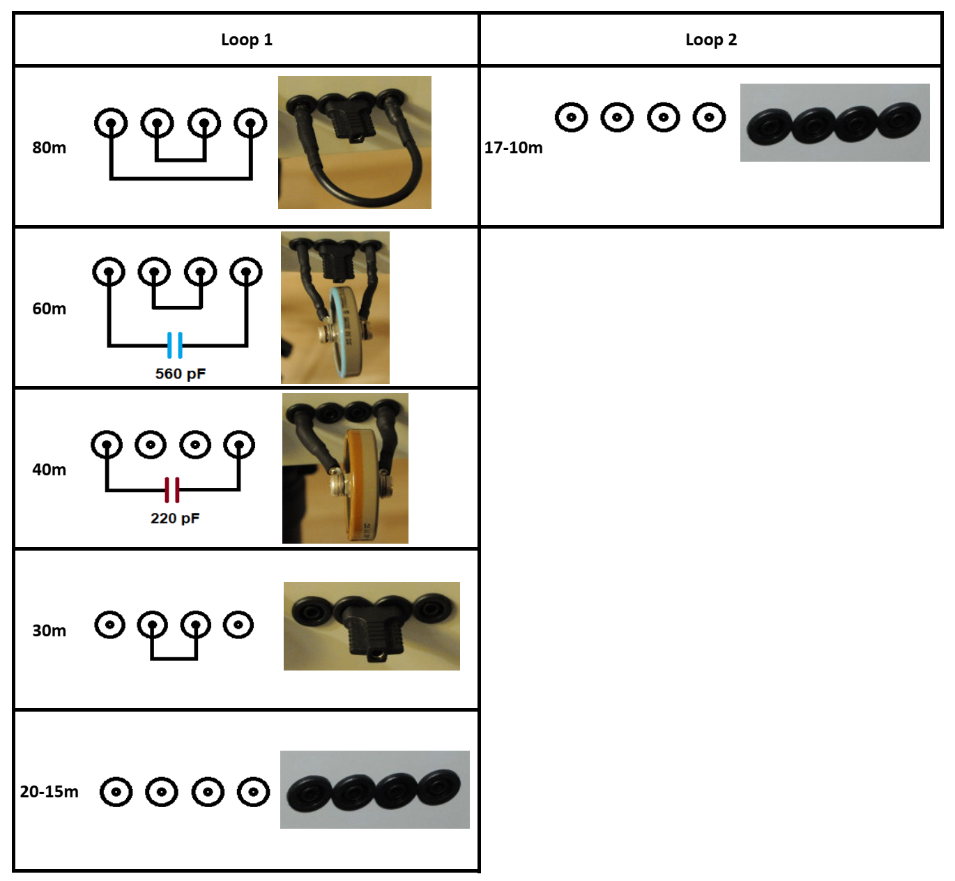
The bands are selected using jumpers. In addition to the jumpers, high voltage external capacitors of 220pF and 560pF are used. The band selection scheme is shown in the figure bellow.

Selecting band with jumpers and capacitors

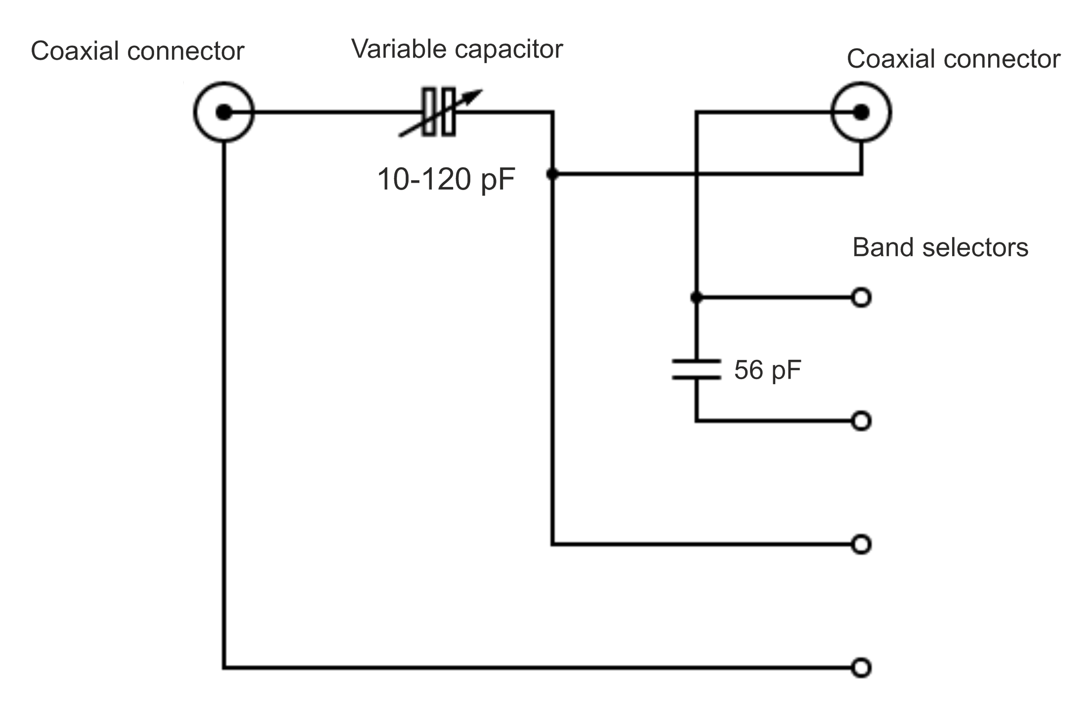
Internal connection of band selector

Remote tuning

The remote control is almost an essential part of the MLA. Because of the need for very precise tuning of the capacitor, it is difficult to tune manually. In addition, a hand near the antenna affects the tuning frequency. This antenna is tuned using a Nema 11 stepper motor with a 1:100 gear ratio, the end positions are treated with limit switches. The control box is connected to the motor via a networking cable. It has the possibility of coarse and fine tuning, the display shows the position of the capacitor and the approximate tuning frequency with the possibility of calibration. Hardware includes an input power filter, Arduino Nano Every microcontroller, DRV8825 stepper motor driver, rotary encoder, buttons, LEDs and TFT display.

The disadvantage of stepper motors with gearbox is the gearbox backlash, which must be solved in software. In SW I add extra steps when changing direction to compensate this backlash. If you are interest in my SW, I will try to make public version in future.


Conclusion

This 100W MLA antenna is ideal for radioamateurs who cannot have their own antenna located outdoors. I had a lot of fun with it, especially on 80m, on my previous QTH where there was no option to place a wire antenna. It’s more suitable for CW/FT8 operation, but I’ve also made contacts with it on SSB, but on 80m it already has a small bandwidth and tuning can be more difficult. The antenna can be easily disassembled and stored e.g. under the bed. The frequency tuning indicator is useful, on lower bands it is rather approximate, the frequency is affected by nearby metal objects. It is necessary to keep away from these objects, they may even make it impossible to tune the antenna. For this reason it is not possible to operate the antenna e.g. on a balcony with a metal railing. Minimum distances from the antenna must be kept in relation to the power used.

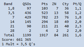
CQ WPX CW 2022

CQ World Wide DX Contest

CALLSIGN: OL2J
TRX: Kenwood TS-480sat
PWR: 100 W
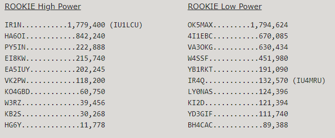
CATHEGORY: Rookie Low Power (All Band Assisted)
MODE: CW
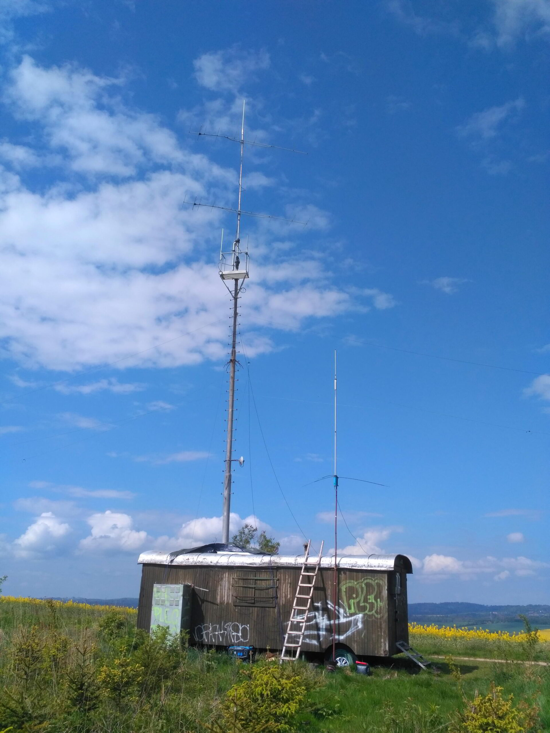
QTH: Czech Republic, Jihlava JN79TI, OK2KJI/OL2J contest site – Holý vrch 660m ASL

ANT:
160m – WINDOM
80m – WIRE DIPOLE
40m – WIRE DIPOLE
20m – ROTARY DIPOLE
15m – ROTARY DIPOLE
10m – WINDOM

I would like to thank Robert OK2PYA for help with antenna setup and his advices.

Story (CZE):
V pátek při stavbě antén foukal silný vítr. Zvednout a ukotvit stožárek nebylo v jednom člověku úplně jednoduché. Naštěstí později přijel Robert OK2PYA, který mi pomohl natáhnout drátové dipóly, což jsme stihli akorát než začalo pršet. Tentokrát byl operační čas podstatně kratší, než u předchozích CQ contestů. Hlavně proto, že se mi podařilo obě noci zaspat. Podmínky byly na vyšších pásmech všeobecně horší a QSO přibývaly pomalu. Oproti CQ WPX konaném před rokem na sobě pozoruji posun co se týká CW, čísla mi už moc nedělají problém, jen se mi ještě pletou volačky. Hlavně když už mám pár hodin vysílání za sebou. Celkově mohu říci že moje poslední účast v kategorii Rookie mě zase někam posunula a příště se rád zúčastním už v “dospělácké” kategorii.

Děkuji OK2KKW a OK2BPV za pohlídání stanoviště a mojí XYL za uvaření jídla na celý závod.

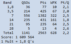
Raw score before checking

QSO by hour

CQ WW WPX 2022 contest in photo:

CQ WW CW 2021

CQ World Wide DX Contest

TRX: Yaesu FT-1000mp
PWR: 100 W
CATHEGORY: Rookie Low Power (All Band Assisted)
QTH:  Jihlava JN79TI, OK2KJI contest site – Holý vrch 660m ASL

ANT:
160m – WINDOM
80m – WIRE DIPOLE
40m – WIRE DIPOLE
20m – ROTARY DIPOLE
15M – ROTARY DIPOLE
10m – WINDOM

I would like to thank Robert OK2PYA for help with antenna setup and his advices.

Declared score

Story (CZE):
Kvůli předpovědi počasí, které mělo v pátek přinést intenzivní sněžení jsem se rozhodli začít se stavbou antén už ve čtvrtek. Byly nataženy drátové dipóly pro 80 a 40m. Akorát jsme je stihli s Robertem OK2PYA instalovat, než byla úplná tma. V pátek byly postaveny rotační dipóly pro pásma 20 a 15m vlastní výroby, které se celkem v OKOMDX contestu osvědčily. Chtěl jsem ještě zkusit natáhnout LW 82 metrů pro pásmo 160m, ale všude už ležela silná vrstva sněhu, stačilo se setmít a jaksi nebylo úplně kam. Nakonec toto pásmo na windomku nechodilo až tak špatně a první hodiny závodu jsem lovil zde. Tentokrát jsem si troufl na výzvu a na 80 a 40m se tvořily zvládnutelné pileupy. Vyhledávání mi naopak moc nešlo a raty šly dolů. Zvlášť dovolávání na vzácné stanice končilo mnohdy po ztracených minutách bez úspěchu. Taktéž pásma 20 a 15m byly první den úplně zabité. Naštěstí druhý den už chodily podstatně lépe a já mohl dohánět chybějící násobiče. Můj cíl byl 1000 QSO a 0,5M bodů. Podařilo se mi navázat 1216 QSO s operating time odhaduji něco přes 36 hodin. Toto je můj poslední CQ WW DX contest, který můžu jet v kategorii Rookie (operátoři vlastnící licenci méně jak 3 roky, v překladu bažanti, zelenáči).

CQ WW DX contest in photo:

My 80-15m MLA antenna with “virtual” capacitor

MLA

MLA base

Introduction

This MLA uses both conductor of coaxial cable. Wiring inner and outer conductor of main loop coaxial cable in series helped me to get on lower bands. It adds “virtual” capacitor and inductance to L/C antenna circuit. I got inspiration from OK2ER and his design of MLA-S antenna that uses this kind of great idea. (The idea is also patented by him as well).

Construction

Main loop is made of 3 m long 7/8″ Cellflex cable, so overall diameter is about 1 m. Outer conductor diameter of 28 mm gives advantage in efficiency of the loop and holds shape very well without any supports. I bought the cellflex cable along with connectors for very pleasent price.

Variable capacitor is butterfly type with capacity of approx. 12-125 pF, rated 3kV. It was bought on lc-variable.eu (the page is no longer active). Capacitor is rotated by Nema 11 stepper motor with 100:1 gearbox. Maybe it is quite overkill ratio, i would be happy with 1:51, 1:25 or just with cheap 28BYJ-48 because capacitor doesn’t need much torque to rotate. Gearbox with motor makes an audible anoying noise (especially for my YL HI) but not big issue. Stepper motor is wired via ethernet cable and remotely tuned. As the variable capacitor can turn 360 degrees, i don’t use limit switches. But you can see an unconnected cable for this purpose ready for future use. I will describe my remote tuner on another post. But briefly, i simply turn the motor for highest amount of noise on my waterfall and than for best SWR.

For holding MLA on its place i use speaker stand (Adam Hall SPS023) with mounting bracket (Adam Hall SPS57) screwed to MLA base. It provides very good stability needed for this quite heavy MLA and it is cheaper than photo tripod suitable for this weight.


Mounting bracket and choke

Coupling loop is formed by RG58 cable. I use shielded coupling loop as you can see on picture. Shape of the loop must be adjusted on particular bands for best SWR. It is done by moving plastic bands. It is possible to get close to 1:1.01 SWR with some effort. I have several winds of coax on Amidon FT140-43 ferite core just for sure.

Faraday coupling loop [1]

Coupling loop 40-20M

Coupling loop for 80, 17 and 15M

Band selector

Tunable range of MLA with variable capacitor itself is 20-15M. To change bands it is necessary to add some fixed or virtual capacitor. This is done by banana plugs. “Virtual” capacitor is not virtual in the meaning of being non-existent, it is in fact formed by coaxial cable of the main loop. Also MLA’s inductance will be increased by using this kind of feature. Following wiring was found by experimentally.

Band selector schematic

Banana sockets

80M band

Fixed capacitor for 40M band

20M band

30M band

40M band

80M band

Performance

Maximum usable power should be around 100 watts but i am limited with my 20 watts rig so i didn’t test it. I use it mostly for CW mode and do QSOs around Europe. On my QTH surrounded by buildings, my favorite bands are 80 an 40 meters. It is an antenna of compromise locked in Faraday’s cage but still able to do QSOs. On picture bellow you can see WSPR running with 5 watts and 20M and 40M band:

WSPR 5W, 40 and 20M band

Conclusion

MLA using “virtual” capacity is an alternative to multiturn loop. Adding more turns to your MLA will lower needed capacitance but increase voltage on the variable capacitor. Here the maximum voltage on variable capacitor is actually lowered. This MLA could be able to get on wider range of bands (80-10M) by reducing diameter of the main loop. Based on OK2ER construction of MLA-S, ideal diameter should be around 80 cm. This concept of using capacitance of main’s loop coaxial cable was described by OK1VR [2] [3] and transformed into easy usable MLA by OK2ER [2] (MLA-S meaning MLA SMART [2]).

References

[1] 80-20m Mag Loop. Nonstop Systems: Consulting Services for the Development of Fault-Tolerant Systems. URL: https://www.nonstopsystems.com/radio/frank_radio_antenna_magloop.htm

[2] Loop2ER – Magnetic Loop Antennas. URL: https://www.loop2er.cz/magnetic-loop-antennas

[3] OK1VR Macoun, J. Magneticka smyckova antena prakticky (3). Prakticka elektronika 2019-10, URL: http://www.crk.cz/FILES/VR-ANT/85.%20Mag9.pdf

[4] OK1VR Macoun, J. Magneticka smyckova antena prakticky (5). Prakticka elektronika 2020-07, URL: http://www.crk.cz/FILES/VR-ANT/88.%20Mag11.pdf